Introduction
Start at Files > Files List to view functions and their documentaion
Setting up CCS for R2R
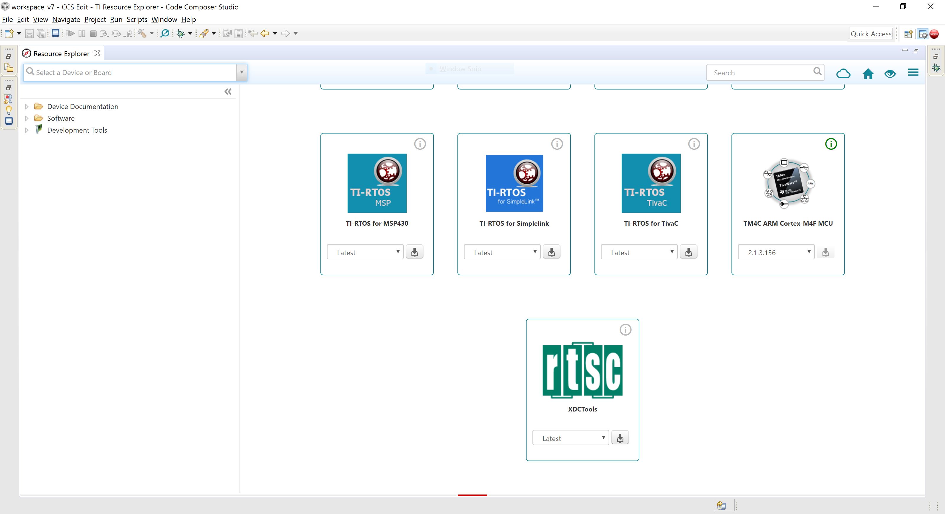
In order to start programming the microcontroller, the user has to install Code Composer Studio (CCS) from TI. In CCS, the TIVAware library has to be installed. This can be done through the Resource Explorer avaliable in CCS. The Resource Explorer can be reached from Help > Getting Started > Browse Examples.
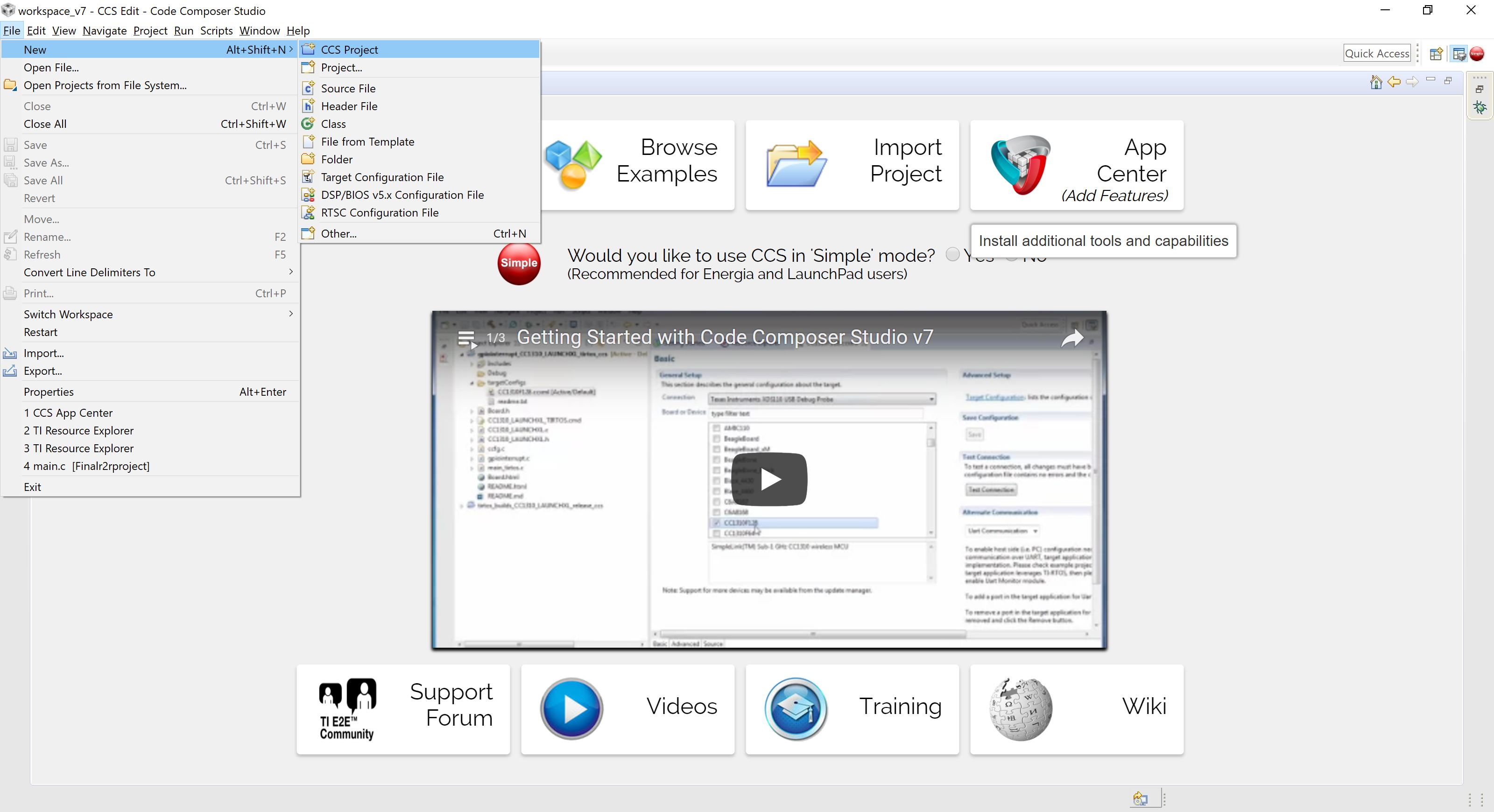
Once the libraries have been installed, create a new project
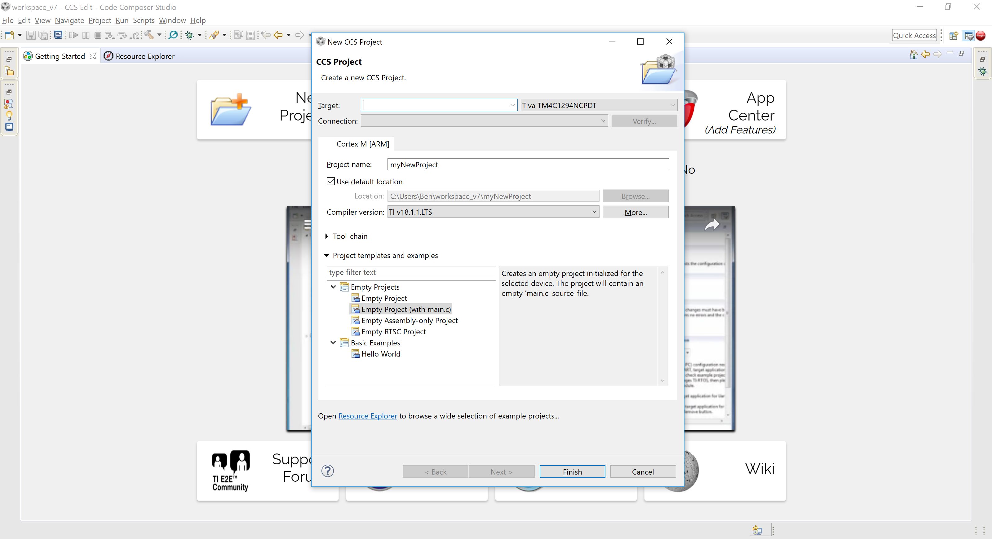
Ensure that the Tiva TM4C1294NCPDT chip is selected and give your project a name. When you are done, select Finish.
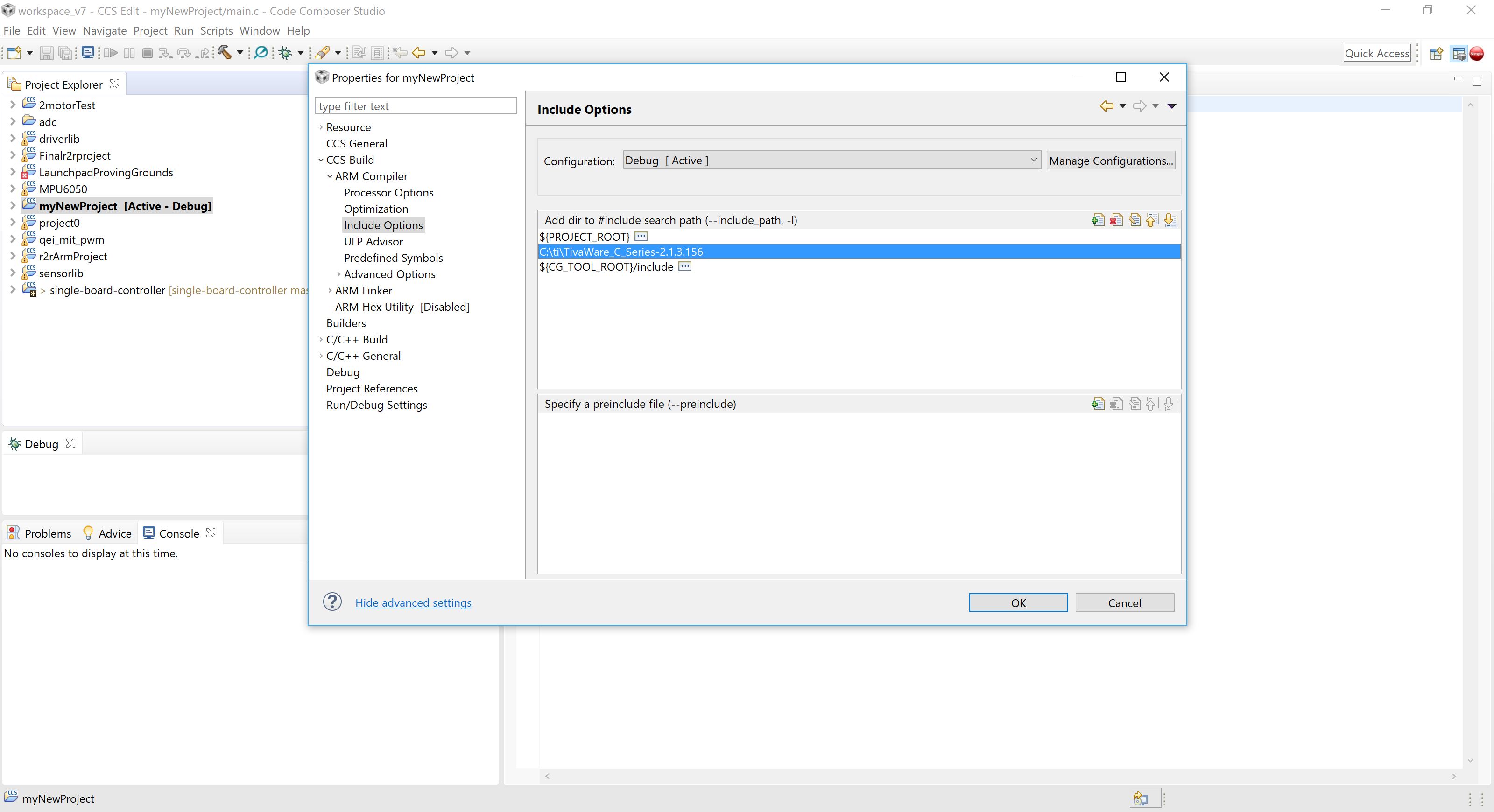
The code perspective will open up. On the left the active project is bolded. Your new project should be bolded. If it is not, select it. Some libraries have to be manually added to the project before the code can run. Right click the project name in Project Explorer, and select properties.
Under CCS Build > ARM Compiler > Include options, include the Tivaware library.
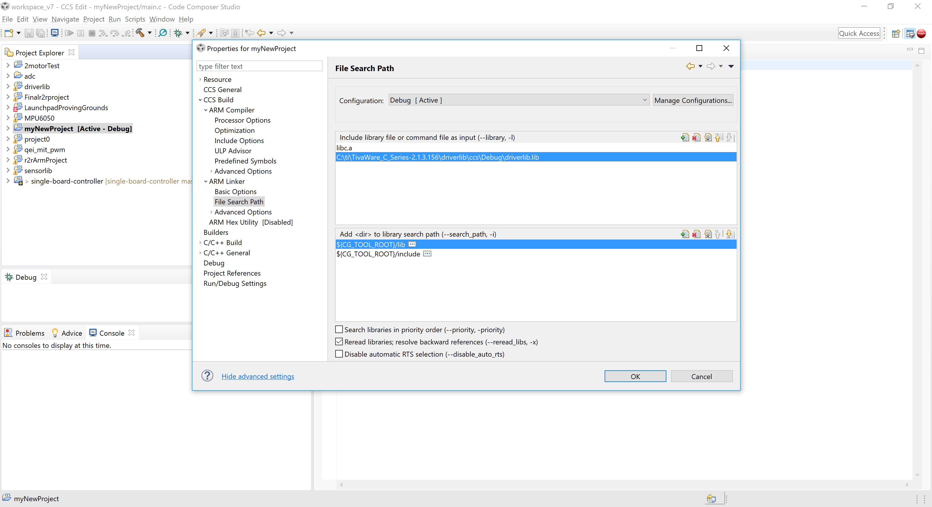
Next, under CCS Build > ARM Linker > File Search Path, include the library files for the driver library, driverlib. The sensorlib files are also included in the same manner.
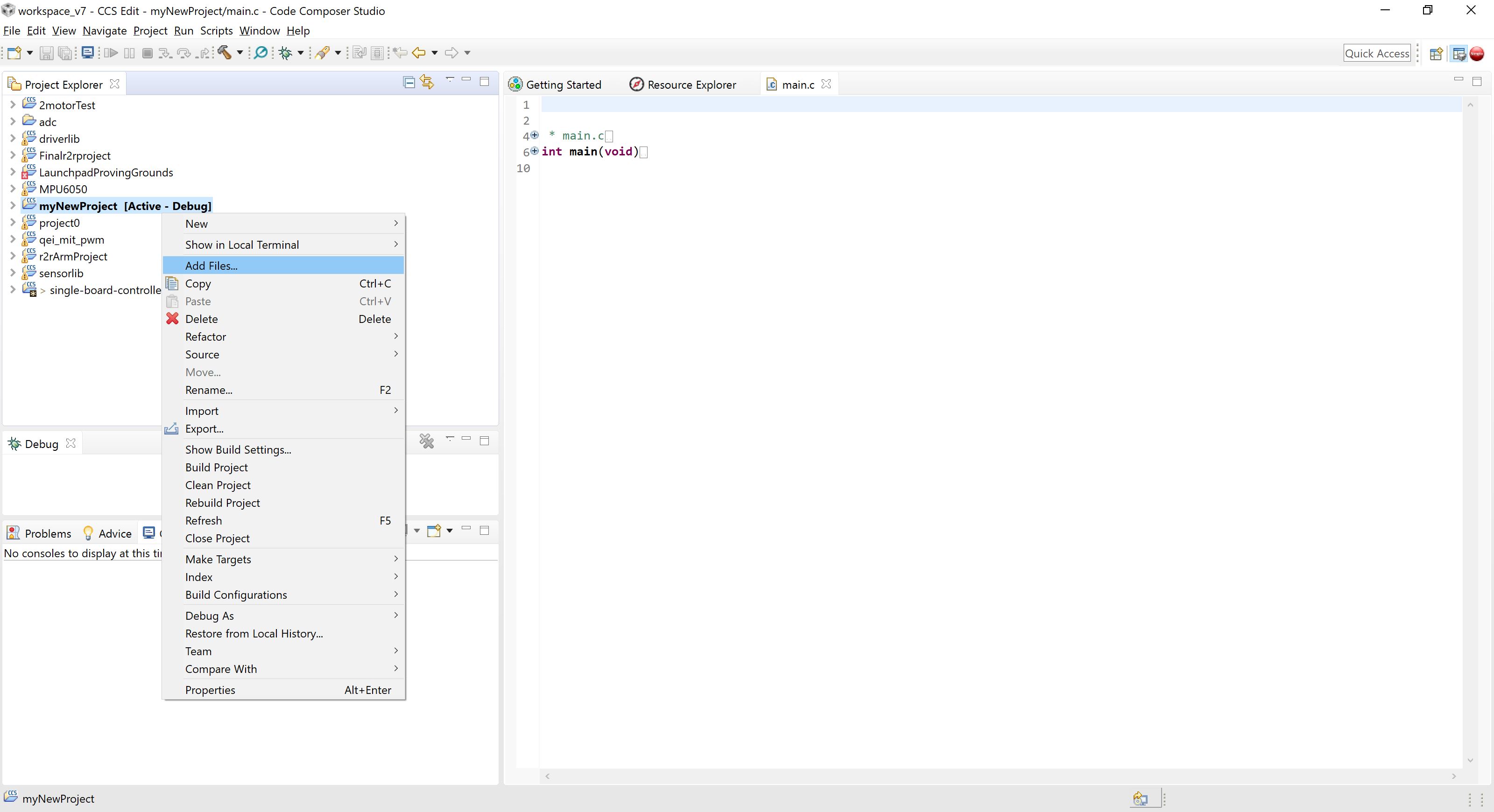
Finally the files from the Github project can be added to the project. Because version control is already managed by Github in this case, the files are linked into the the project. However, the user can also add the files directly into the project.
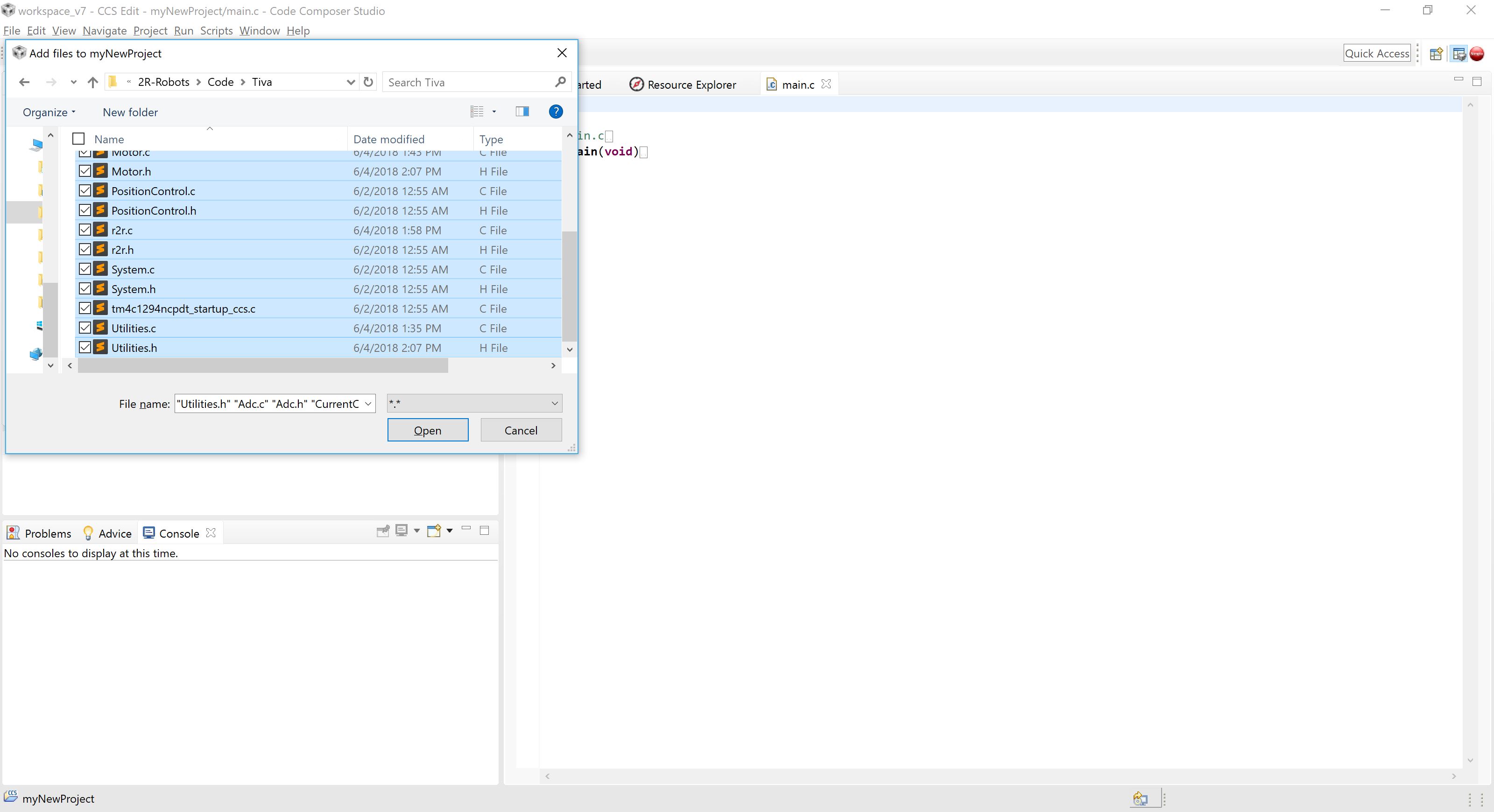
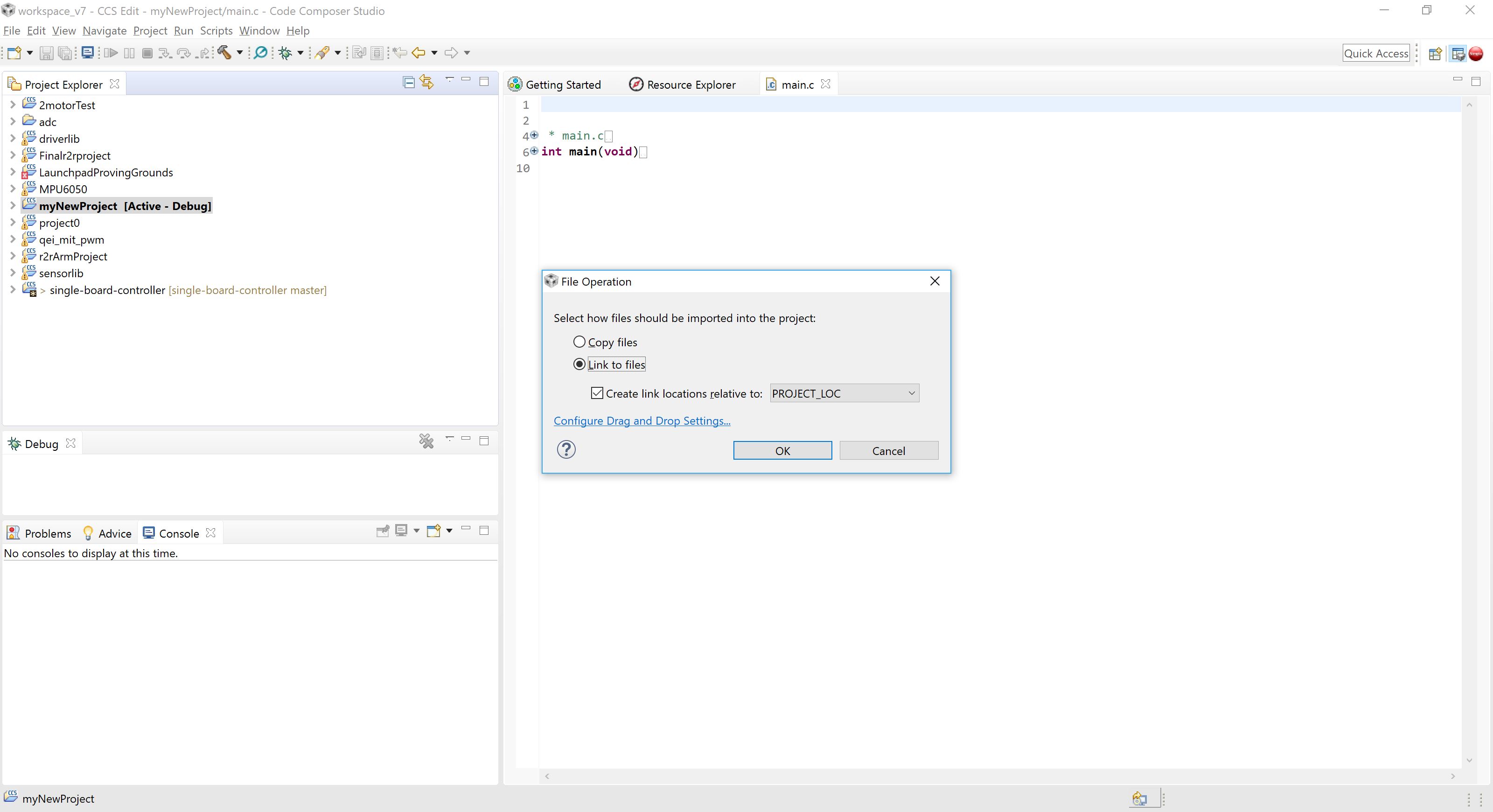
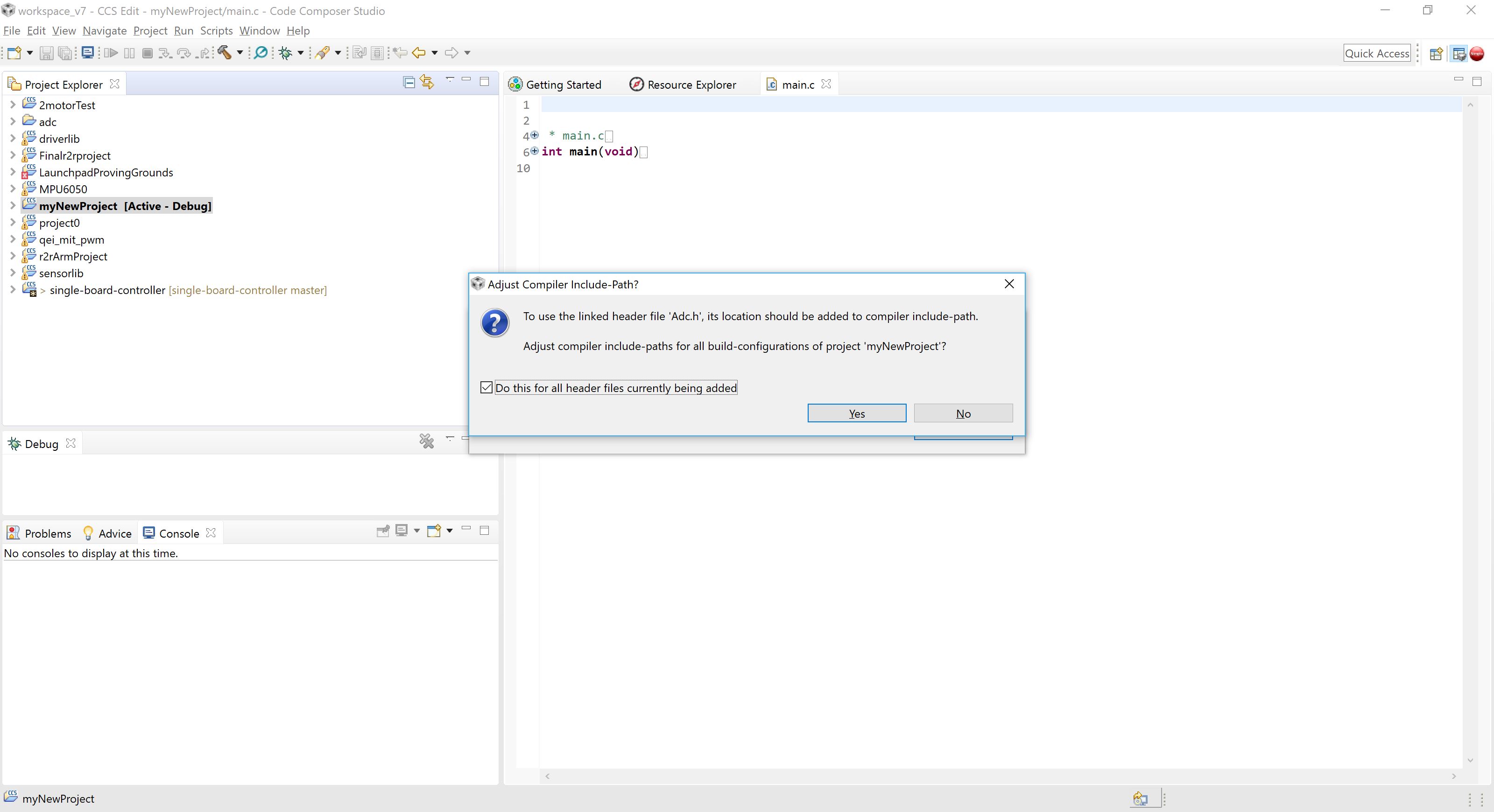
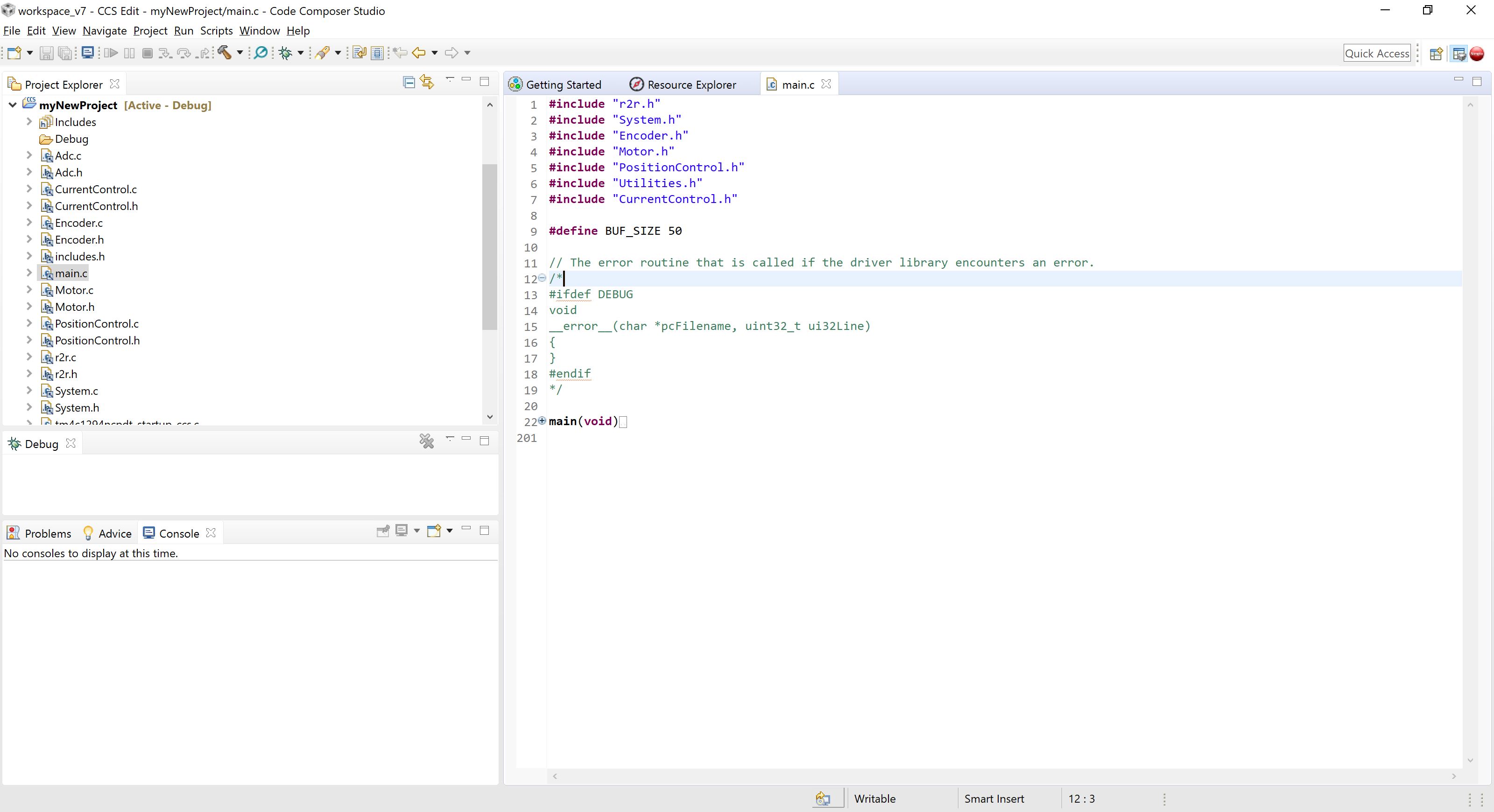
If the files cannot be added, delete the conflicting file in the project and attempt to add the file again. Once all the files have been added, CCS should look like the following state.
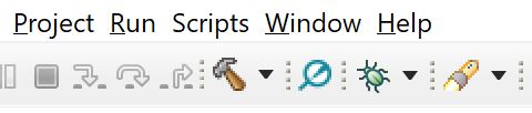
The code is built by clicking on the hammer icon. In order to program the board, the green debug symbol is clicked. Test by compiling the code. It should compile without any errors.
Writing Custom Code
Two timers (Timer 6 and Timer 7) are set up in the code and can execute at user-set frequencies in r2r.c. The intention is that the user will either write code in r2r.c or create a header and source file. Here, an simple example will be set out to compute simple position control over motor 1 in r2r.c at 5kHz.
Writing Interrupts
In Code Composer Studio, interrupts follow a general format. There is the interrupt initialization, the interrupt function itself, and a declaration of the interrupt function in the interrupt vector table in tm4c1294ncpdt_startup_ccs.c.
In this example the timer interrupt has already been declared under customTimersInit() and the corresponding timer functions have been declared in tm4c1294ncpdt_startup_ccs.c.
In r2r.c, update frequency:
#define TIMER_6_FREQUENCY 5000
Add global variables for the PID controller in r2r.c
int int_error = 0;
int prev_error = 0;
Under TIMER6IntHandler() in r2r.c:
void TIMER6IntHandler(){
    float kp = 0.5;
    float ki = 1;
    float kd = 0;
    desired_position = 60; //degrees
    encoderRead(); // update the encoder
    int actual = readMotor1RawRelative(); // read counts set to relative
    int raw = readMotor1Raw(); // read counts absolute
    int error = angles2Counts(desired_position) - actual;
    int u = kp*error+kd*prev_error+ki*int_error;
     int_error = int_error+error;
     prev_error = error;
    motor1ControlPWM(u);
 }
UART communication
In order to communicate over UART, several functions are provided under systemInit(). In the default case, the UART is already initialised to a baud rate of 115200, 8N1 mode. This example will use a polling method to process input from the user.
First set up a global variable in main.c that will be used to store the desired angle:
volatile int setAngle = 0;
In main.c, under main():
    int main(void){
    char buffer[50]; // set up a char buffer

    while(1){ // set up an infinite loop

        UART0read(buffer); // read the buffer
        scanf("%d",setAngle);
        sprintf(buffer,"Okay! Setting to: %d",setAngle) // acknowledge
        UART0write(buffer,50); // write to the buffer

    }
}
Add a global variable in r2r.c to refer to the setAngle variable we just created in main.c:
extern int setAngle;
Now we have to modify the code in the TIMER6IntHandler() to refer to this variable:
void TIMER6IntHandler(){
    float kp = 0.5;
    float ki = 1;
    float kd = 0;
    desired_position = setAngle; //degrees
    encoderRead(); // update the encoder
    int actual = readMotor1RawRelative(); // read counts set to relative
    int raw = readMotor1Raw(); // read counts absolute
    int error = angles2Counts(desired_position) - actual;
    int u = kp*error+kd*prev_error+ki*int_error;
     int_error = int_error+error;
     prev_error = error;
    motor1ControlPWM(u);
 }
Writing Menu Commands
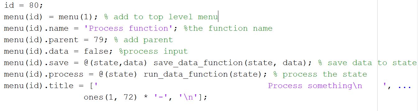
The MATLAB menu can also be modified to fit a custom control law. The MATLAB code is set up in a tree format where each entry is a node that includes information about its parent and children. The only point to edit is * where the details of the node has to be specified
There are two types of nodes: a data node, which accepts input from the user and immediately transitions to its child node, and a navigational node, which accepts input from the user and checks its child nodes for the matching option. The navigational node does simple error checking, but the data node does not because of the wide variety of data types that might be possible. Instead, a statement of the expected data type is presented and the user is expected to conform to this data type when interacting with a data node.
On the firmware side, additional case statements are added that correspond to the added nodes to process the incoming data.
The user has to add in two functions, one which saves the input to the state of the program, and the other which processes the input. The only function that needs to be edited is the hierarchicalMenu.m, which is found in: BackupAndUI > R2R_interfaces > menu_library
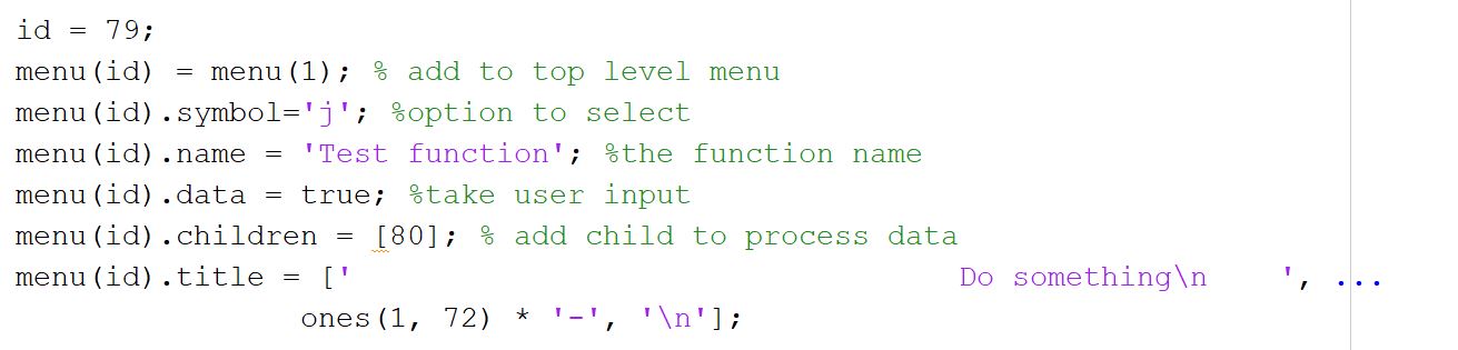
Once the top level menu option has been created, a menu function to process the data must also be created.